In order to reevaluate the prototype/deflection hypothesis it is necessary to first review the categories and orientations of “directions” as conceived in choreutics. These consist of directional lines which are joined together to form conceptual kinespheric networks (see IIIC.30).
IVA.21 Undifferentiated Spherical Conception of Space.
The most basic conception of space is as a sphere. This “imaginary sphere” is conceived as a “sphere around the body whose periphery can be reached by easily extended limbs” and is termed the “kinesphere” (Laban, 1966, p. 10; see IIB.38).
A sphere is undifferentiated except for its centre and its periphery. A distinction is made between 1) lines which lie along the edges of the kinesphere, 2) lines which pass through the kinesphere and intersect its centre and 3) lines which pass through the kinesphere but do not intersect its centre (Laban, 1966, p. 68). These are referred to as “peripheral”, “central”, and “transverse”* respectively (Bartenieff and Lewis, 1980, p. 107; Preston-Dunlop, 1984, p. viii).
There are no other landmarks or orientation points available within this generalised spherical spatial conception. Thus, for greater definition of areas, zones, and directions in space, the sphere must be divided into distinct parts.
__________
* It is evident from Laban’s (1966, p. 68) discussion that dimensions, diagonals, and diameters are different from “‘transversals’” or peripheral “surface lines”. This distinction is not maintained here because in many cases transverse lines or peripheral lines are parallel to a dimension or a diameter and all parallel lines are considered to be in the same “direction”. This necessitates using the terms “peripheral dimension” and “transversal dimension” (as opposed to a “transversal inclination” ) (eg. Ullmann, 1966, pp. 165-166, 181-184). In this paper the terms “central”, “peripheral” and “transverse” are used to describe the relationship to centre of any direction. Thus, a “dimension” is not necessarily different from a “transversal”.
__________
IVA.22 Dimensions.
IVA.22a Three dimensions.
The fundamental directions used in all types of spatial conception and also within choreutics are the three dimensions (referred to here as lateral, vertical, and sagittal*) which correspond to the Cartesian x, y, and z axes. Laban (1966, p. 11) refers to the three dimensions as the “basic elements of orientation” and that the solid object which contains the three dimensions and is “easiest to visualize, is the cube”. Thus, the cubic, dimensional conception of space is envisaged as the simplest, most prototypical, division of the sphere into differentiated regions.
The spheric form of the kinesphere is simplified [differentiated] by our cubic conception of space. We recognize the cube inside the kinesphere as being representative of the most important space directions. (Laban, 1966, p. 18)
__________
* To avoid confusion it is desirable that different names be used for the dimensions versus the Cartesian planes. The dimensions are referred to here as “vertical”, “lateral”, and “sagittal” while the Cartesian planes are referred to as “frontal”, “medial”, and “horizontal” (see Appendix VIII).
__________
Laban (1966) goes on to describe how the three dimensions are evident within the structure and function of the human body. The “simple one-dimensional vertical” is described as the “fundamental structural extension of the body” (p. 18), that is, the body’s structure is extended along this dimension more than any other. The lateral dimension or the “bilateral extension” is considered to be the “second extension which we feel [which] originates from the bilateral organisation of our body, caused by the mirror-like structure of the left and right sides” (p. 18). The sagittal dimension is mostly evident in the function rather than the structure of the body. This “third dimension becomes apparent only when moving . . . when stepping or reaching and grasping, and manipulating objects” (p. 19).
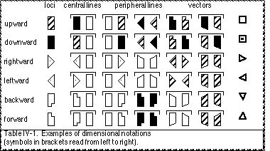
“Each ‘dimension’ has two directions” and these are referred to as the “‘dimensional directions’” (Laban, 1966, pp. 11, 14). Various terminology can be used for the dimensional directions (eg. deep, low, down, and downward can all refer to the same direction). They will be referred to here as upward, downward, rightward, leftward, forward, and backward. Dimensional directions can be notated in various ways. Table IV-1 lists some possibilities for notating limb paths and poses as dimensional points with a single direction symbol, as dimensional lines of motion with pairs of direction symbols, and as the line of limb motion (regardless of particular positions) with vector symbols.
IVA.22b Dimensional Cross and Octahedral Network.
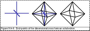
When the three dimensions are arranged to intersect at the centre of the kinesphere Laban (1966) refers to them collectively as the “dimensional cross” (pp. 13–16). This is identical with the Cartesian cross when it is aligned with the body’s anatomy. When the end-points of the dimensional cross are connected, they form an octahedral-shaped kinespheric network (p. 103) (Fig. IVA-9).
IVA.23 Diagonals.
IVA.23a Pure diagonal directions.
The concept of “diagonal” has a specific meaning in choreutics. Laban (1966) describes each of the diagonals* as “a kind of axis” between the three dimensions such that a diagonal is “surrounded by three dimensions” (p. 11). Therefore, a “pure diagonal” is described as a “space–direction which stresses all three dimensions equally strongly” (Ullmann, 1966, pp. 143-144; also Bodmer, 1979, p. 14) and refers to how a diagonal line is oriented at a 45° angle to each of the three dimensions. This means that a choreutic pure diagonal does not lie within any of the Cartesian planes. This specific definition of “diagonal” in choreutics is different than its usage in modern-day Labanotation, in common dance terminology, or its typical definition in every-day language.
__________
* Rarely, Laban (1966) refers to pure diagonals as “‘diagonal inclinations’” (p. 15) but the term “inclination” is usually used in choreutics in a more specialised sense and this will be maintained here (see IVA.25).
__________
In Labanotation the term “diagonal” is used to refer to directions which “lie exactly between forward and side directions . . . or between backward and side directions . . . and not for a gesture which is slanting upward or downward” (Hutchinson, 1970, p. 25). Thus, the right–forward, left-forward, right-backward, and left-backward directions in the horizontal plane are considered to be “diagonals”. Laban (1966, p. 13) refers to these four horizontal planar directions, together with the choreutic diagonals, collectively as “oblique directions” whereas Hutchinson (1970, p. 25) uses the term “oblique” to refer only to the up/down slanting of the choreutic diagonals.
In common language (Collins, 1986) and in everyday dance terminology the concept of a “diagonal” refers to any type of oblique slanting, whether it is within a Cartesian plane or not. Likewise, Bodmer (1979, p. 14) uses the term “plane diagonals” to refer to the slanting directions which lie within a Cartesian plane.
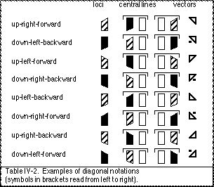
Each of the four choreutic pure diagonals can be produced in either of two directions. These eight diagonal directions do not have individual names and so are referred to in terms of their dimensional content. Table IV-2 gives examples of diagonal directions notated as directional points, directional lines and vectors.
IVA.23b Diagonal cross and cubic network.
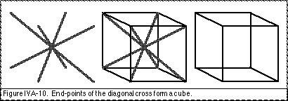
When the four pure diagonals are arranged to intersect at the centre of the kinesphere Laban (1966) refers to them collectively as the “diagonal cross” (pp. 14, 16). When the end-points of the diagonal cross are joined together they form a cubic–shaped kinespheric network (p. 104) (Fig. IVA-10).
IVA.24 “Diameters”, Primary Deflections.
The term “diameters” is used in choreutics to refer to directions which are oriented obliquely across one of the Cartesian planes, thus they have also been referred to as “plane diagonals” (Bodmer, 1979, p. 14). The exact orientation of the diametral directions is a principal topic of the prototype/deflection hypothesis (see IVA.40; IVA.82). Because of this importance given to the twelve diametral end-points they are sometimes referred to as “signal-points” (Laban, 1966, pp. 82, 85, 101).

Two orientations of diameters are commonly used in the choreutic conception. “Primary deflected diameters” are oriented relative to a cuboctahedral network, and “modified diameters” are oriented relative to an icosahedral network.
IVA.24a Primary deflected diameters, Square Cartesian planes.
Laban (1966) describes one group of diameters as “axes which lie between two diagonals and two dimensions” and so are considered “to be ‘deflected’ from the dimensions or from the diagonals” (p. 11) and so are referred to as “deflected directions”, “diametral inclinations” or “primary deflected inclinations”* (pp. 15-16). The primary deflected diametral directions are each conceived to be oriented at a 45° angle from each of the two dimensions within a Cartesian plane. When the end-points of the primary deflected diameters within the same Cartesian plane are connected they create a square-shaped plane (Fig. IVA-11).
__________
* Rarely, Laban (1966) refers to diameters as “‘diametral inclinations’” (p. 16) but the term “inclination” is usually used in choreutics in a more specialised sense and this will be maintained here (see IVA.25).
__________
IVA.24b Modified diameters, Rectangle Cartesian planes.
As part of the prototype/deflection hypothesis (see IVA.40) the orientation of the diameters is conceived to be shifted slightly and these are referred to as “modified diameters” (Laban, 1966, pp. 101-102). The frontal planar diameters deflect toward the vertical dimension, the horizontal planar diameters deflect toward the lateral dimension, and the medial planar diameters deflect towards the sagittal dimension. As a result “the pull of one of the dimensions in each plane is dominant over the other” (Bartenieff and Lewis 1980, p. 32). The proximity of diametral directional points to the dimensions is notated in Table IV-3.
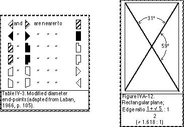
The modified diameters are oriented at an approximate 31° angle to one dimension and 59° to the other dimension (for details, see Appendix X). If the end-points of the modified diameters are connected they create a rectangle-shaped Cartesian plane (Fig. IVA-12) which has the proportions of the “golden section”.
Sometimes the orientation of the modified diameters is conceived as resulting from a division of each of the dimensions (rather than a shifting of the diameters) (Laban, 1926, pp. 22-23; Preston-Dunlop, 1984, pp. 21-22; Ullmann, 1955, pp. 29-31; 1966, pp. 139–142; 1971, pp. 18-21). According to this conception “The three dimensions [each] have a double consequence” (Laban, 1926, p. 22) resulting in a “split of the one dimensional” and so “the dimensions are not felt by the body as lines but as planes” (Ullmann, 1966, p. 141). Accordingly, the planes created by modified diameters are sometimes referred to as “dimensional planes” in which one dimension is the “primary one” and the other dimension in the plane is the “secondary one” (Laban, 1926, p. 23; Ullmann, 1966, p. 142). The vertical dimension is conceived to widen slightly into the frontal plane, the lateral dimension bulges slightly into the horizontal plane, the the sagittal dimension extends into the medial plane (for description see IVA.82).
IVA.24c Diametral crosses, Polyhedral networks.
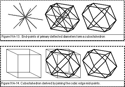
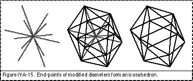
There are six diameters (two diameters within each Cartesian plane). When these are arranged to intersect at the centre of the kinesphere they can be referred to collectively as the “diametral cross” (Laban, 1966, pp. 15–16). When the end-points of the primary deflected diametral cross are joined together they form a cuboctahedral-shaped kinespheric network (Laban, 1966 p. 104) (Fig. IVA.13). This cuboctahedron net can be conceptually simplified by regarding it as derived from a cube (Fig. IVA.14) and so primary deflections might be referred to as cubic diameters, or as cuboctahedral diameters. When the ends of the modified diametral cross are joined together they form an icosahedral-shaped kinespheric network (Fig. IVA.15). These can be referred to as icosahedral diameters.
IVA.24d Notation of diametral directions.
Each of the six diameters can be produced in either of two directions. This yields a total of twelve diametral directions. The diameters are referred to in terms of their dimensional content. The primary dimension in an icosahedral diametral direction can be indicated by underlining (following Laban, 1966, p. 102).
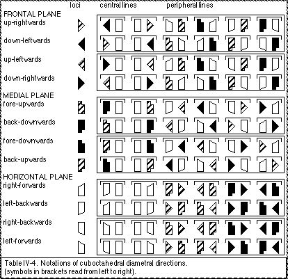
Examples of notations for cuboctahedral diametral points and diametral lines are given in Table IV-4. Peripheral lines in the cuboctahedral net are parallel to the central directional lines and so are included as examples of the same diametral direction.
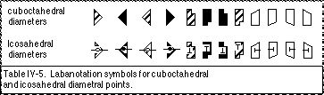
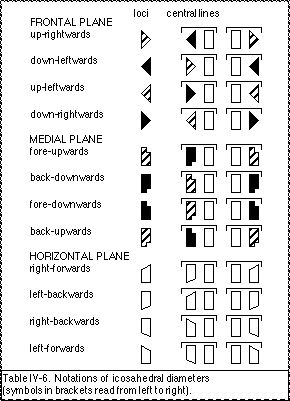
Labanotation direction symbols indicate cuboctahedral diametral directions (ie. 45°) (Hutchinson, 1970, p. 25). However, in choreutic texts (Preston-Dunlop, 1984) and in common practice, the Labanotation direction symbols are also used to indicate icosahedral diametral directions (Laban, 1966, pp. 104-105). Icosahedral diametral directions could be correctly notated with Labanotation “third way points” (Hutchinson, 1970, p. 439) (Table IV-5). However, in interests of simplicity the same direction symbols are typically used for both types of diameters and this will be followed here. Icosahedral diameters can be specified by using a special “icosahedron” symbol (eg. Maletic, 1950), or this can be indicated verbally in the description of the notation. Examples of notations for icosahedral diameters are given in Table IV-6. In contrast to the cuboctahedron, peripheral lines in the icosahedral net are “tertiary deflections” (see IVA.25c) and are not parallel to the central diameters.
IVA.25 “Inclinations”, Secondary and Tertiary Deflections.
Diameters were conceived as “primary deflections” (see IVA.24a) in which a dimension tilts to a certain degree within a Cartesian plane. Secondary and tertiary deflections are also conceived as intermediary directions between dimensions and diagonals. These directions do not lie within or parallel to a Cartesian plane, nor is it parallel to a diagonal, but will “always connect two end-points of two different diameters” (Laban 1966, p. 68). These are referred to as secondary (cuboctahedral) and tertiary (icosahedral) deflected directions. Since these play a special role in choreutics they are referred to collectively as “inclinations”.*
Laban explains that an inclination could be conceived as either a dimensionally-deflected-diagonal or a diagonally-deflected-dimension but that the former is conceptually easier:
There appear two possibilities: To put forward either a diagonal deflected through a close-by dimensional, or alternatively, a dimensional deflected through one of the closest diagonals. Since to us the dimensional-concepts are more familiar, we shall relate the positional-inclinations to these. (Laban, 1926, p. 13)
__________
* In rare cases pure diagonals or diameters have also been referred to as “inclinations” in order “to denote a digression from the . . . dimensional cross” (Laban, 1966, pp. 15, 16). This is closest to the dictionary definition of “inclination” as “the degree of deviation from . . . a horizontal or vertical plane” (Collins, 1986), that is, any non-dimensional line. However, in choreutic practice the term “inclination” has become specialised to refer to a direction which is deflected from a diagonal toward one of the dimensions (Dell, 1972, p. 11; Preston-Dunlop, 1984, p. ix; Ullmann, 1966, p. 145; 1971, p. 17) and this definition is used here.
“Transversal” is sometimes used synonymously with “inclination” (Dell, 1972, pp. 11-12; Ullmann, 1966, p. 152; 1971, p. 25). This equivalence is rejected here since “central inclinations” and “peripheral inclinations” can occur which are not transverse and a “transversal dimension” may occur which is not an inclination (Salter, 1977, p. 134; Ullmann, 1966, pp. 147, 165, 173, 184).
Inclinations could also be referred to collectively as “deflections” since they are deflected from a diagonal and a dimension. The notion of “deflection” is kept distinct here as a reorientation process, for example diameters can also be considered to be deflected from dimensions.
__________
IVA.25a Flat, steep, and suspended inclinations.
The directions of the secondary and tertiary deflections is defined according to their dimensional content. When an inclinational line is oriented primarily along one of the dimensions then it can be called a deflection of that dimension (and the closest diagonal). The three possible dimensional deflections are referred to as “flat” (lateral deflection), “steep” (vertical deflection), or “suspended”# (sagittal deflection) (Bartenieff and Lewis, 1980, p. 40). Each of the four diagonals can be deflected by either the lateral, vertical, or sagittal dimension yielding a total of 12 inclinations.
__________
# The English term “flowing” was chosen by Laban (eg. 1966, p. 74) for a sagittal deflection but “suspended” will be used here (following Bartenieff and Lewis, 1980, p. 40) so as not to create confusion with Laban’s conception of the movement’s “effort” quality referred to as “flow” (Laban and Lawrence, 1947). The original German term, “schwebende” (Laban, 1926, p. 44), from Schwebe, refers to a quality of hanging, hovering, floating, suspense (Collins, 1969).
__________
IVA.25b Secondary deflections, Cuboctahedral inclinations.
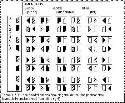
Laban (1966) considers inclinations within a cuboctahedral network* to be “‘secondary deflections’” (p. 68) or as “secondary deflected inclinations” (p. 73). A total of 24 transverse lines can be constructed by linking pairs of loci within a cuboctahedral network. These can be grouped into 12 pairs of parallel lines, each pair being in the same direction (and so the same inclination). This yields 12 possible inclinations within the cuboctahedral network (Laban, 1966, p. 73). Each inclination can be executed in two directions, thus yielding a total of 24 secondary deflected directions. Examples of the secondary deflections are notated in Table IV-7. Inclinations in the cuboctahedral net are transverse. Peripheral lines in the cuboctahedral net are parallel to the diameters and so are primary deflections (see IVA.24d).
__________
* It is clear that Laban’s (1966, p. 68 et seq.) discussion is in reference to a cuboctahedral network since he refers to its “24 surface-lines” (the icosahedron has 30) and the many parallel relationships reviewed between the central diameters and peripheral directions are true for the cuboctahedron but not the icosahedron.
__________
IVA.25c Tertiary deflections, Icosahedral inclinations.
“The inclinations in the icosahedron are [referred to as] ‘tertiary deflections’ from the diagonals and dimensions”, as “tertiary deflected diagonals” (Ullmann, 1966, pp. 145-146), or sometimes as “modified diagonals” (Bartenieff and Lewis, 1980, p. 33; Dell, 1972, p. 11).
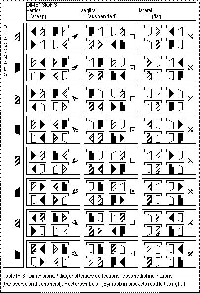
A total of 30 transverse lines can be constructed by linking pairs of loci within an icosahedral network. These can be grouped into 15 pairs of parallel lines, each pair being oriented along the same direction. These 15 directions can then be grouped into 3 transverse dimensions and 12 transverse inclinations. This yields 12 possible inclinations within the icosahedral network. Each inclination can be produced in two directions, thus yielding a total of 24 possible tertiary deflected directions. Examples of the tertiary deflections are notated in Table IV-8. Peripheral lines in the icosahedral net are parallel to the transverse inclinations and so are also considered to be tertiary deflections. Vector symbols can also be used to notate tertiary deflections without regards to specific locations.
IVA.25d Slopes of secondary and tertiary deflections.
A fundamental difference between cuboctahedral inclinations (secondary deflections) and icosahedral inclinations (tertiary deflections) is that they have different slopes, or a “different degree of inclination” (Ullmann, 1966, p. 145).
The slope of a line is typically calculated within a single plane as:
This gives a “numerical measure of the inclination or steepness of the line” (Munem and Foulis, 1986, p. 137). This formula for the slope in two-dimensions can be expanded to three-dimensions by including an additional “run”, thus:
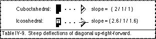
This can be used to compare the slopes of cuboctahedral versus icosahedral inclinations. The steep deflection of the diagonal up-right-forward can be considered as an example. The slope of the cuboctahedral inclination (secondary deflection) is: {2/1/1}; whereas the slope of the icosahedral inclination (tertiary deflection) is approximately: {2.6/1/1.6} (Table IV-9).
Both slopes have the largest proportion of vertical rise which identifies them as steep deflections. The lateral run and the sagittal run are equal in the cuboctahedral inclination whereas the lateral run is smaller than the sagittal run in the icosahedral inclination. These three uneven components of the slope of an icosahedral inclination are described as the “uneven stress on three spatial tensions” (Dell, 1972, p. 10), as “three unequal spatial pulls” (Bartenieff and Lewis, 1980, p. 38), as “primary, secondary, [and] tertiary spatial tendencies”* (pp. 92-93) and so as “extremely” , “somewhat”, or “scarcely” “outspoken”# (Laban, 1926, pp. 25-26).
__________
* These primary, secondary, and tertiary spatial components of an icosahedral inclination should not be confused with the primary, secondary, and tertiary deflections.
# The German “ausgespragt”, translated as “outspoken”.
__________